![]()
![]()
An optocoupled audio interface between PC and Transceiver for digital modes
Radios and computers has a love-hate relationship. Love because I firmly believe that radiocommunications will become fully digital shortly. But computer electronics (high speed, square-waved, spiky, complex…) and radioelectronics (weak signal, high power, high amplification) hate a bit each other. Neverthless they has to coexists for our fun! One of the most common path to interface a radio with a computer is via audio signals and direct connection lead to very well known problems. Common “interfaces” between PC and RTX are made by galvanic isolation operated by transformers. On the market, however, are available optical isolators for high precision signal conditioning that are too sophisticated (and too expensive) for an audio signal such as the one coming from a RTX operating in the amateur band. So I decided to try to build an audio optical isolator using low cost components. The other goal of this project is to have a board readly adaptable to many RTX and PC setup.
If you try to drive an optocoupler emitter with an audio signal (after a suitable polarization, obviously) you get on the optocoupler receiver a very distorted signal; for this reason optocoupler are used (at least up to now) mainly for digital signaling.
But if you try to take a look at modern optocoupler such as Avago/Broadcom HCNR200 you can find a device which incorporate one emitting diode and two almost identical photodiodes that also receive the same light from the emitter.
So it’s easy to image that one photodiode can be used to transfer information between the galvanic isolated parts and the other to linearize all the elctro-optical components. Let me explain it more clearly.
In figure [1] and [2] I’ve reported two applications hints that you can find in figure 12 and figure 16 of the above data-sheet.
In figure [1] we can see that op-amp U1 work with negative feedback through the optocoupler emitter OC1A and the first opotcoupler receiver OC1B. Here’s a quick explaination: let’s suppose that voltage on pin 1 of U1 lower, so current in OC1A will increase. This leads to a more intense ligth emission by OC1A and more currunt will flow through OC1B so reducing voltage on pin 2 of U1 that’s the inverting input. This lead to an increase of voltage on pin 1 compensating the supposed decrease on pin 1 from which we started our analysis. (Ok, if op-amps are ideal we should describe this mechanism in a slight different way but, for simplicity, think to a very large gain differential amplifier)
So the left part of the circuit is stable due to negative feedback. And since op-amp has a very high gain pin 2 of U1 (inverting input) has the same potential of pin 3 (non inverting input), i.e. ground. So input current, that’s Vin/R1, will flow through OC1B (remember that op-amps sinks no current from their inputs). Now look at OC1C: since it receive the same light of OC1B, and it’s pratically identical to OC1B, in OC1C will flow the same current that flow in OC1B, i.e. Vin/R1. Now out voltage, Vout, will be (as in every inverting op-amp configuration) given by Vi/R1*R3. We have an isolated amplifier that works just like a simple inverting op-amp!
But since we don’t need all the features of an op-amp in this simple circuit it’s possibile to realize the same functions with a couple of transistors for each side, just like in figure [2]. This version is fast, accurate and count very few parts and are also cheaper than a couple of op-amps.
To be able to use this principle schematic we need to bias the input of figure [2] and superimpose the audio signal, possibly adjusting the signal level.
A complete board, able to work with both an RX and a TX, needs: two complete stages such as in figure [2], one for RX and one for TX both with polarization network and signal level adjustment, a PTT interface and some power supply regulator. As in the complete schematics in figure [3].
Here Q1 to Q8 implements the two principle schematic of figure [3] using four 4N25 (U1, U2, U3 and U6) as optocouplers. Optocouplers will be slightly different each other but this leads to a minor distortion so it’s not necessary to use hard to find and expensive double receiver optocoupler like HCNR200.
PC-side sensitivity has been settled to standard level for usual soundcards, while on the RTX-side two trimmer are present to adjust very different levels that may be present. Next, if you don’t need to change levels frequently, R22 and R32 can be removed and substituted with a couple of fixed resistors (R19, R22 and R30, R31, rispectively) of the same value you can measure between terminals 2-1 and 2-3 of R22 and R32.
PTT control is issued via uart-over-usb RTS signal using an USB to UART bridge of very common use, an FT230X. The same IC provide PC-side power supply for isolators stage. Should not be an issue with PC driver for this chip, under linux they are native.
Modern RTX has a low level PTT control and, usually, a switch toward the ground capable of few mA is enough. So a fifth optocoupler (U6 in figure [3]) is connected between RTS and PTT. Note: a 4N25 is not suitable here due to low gain, an H11AG1 do the task.
Also on RTX-side we need to power isolators stage: a simple linear regulator give +5V from RTX (usually +12V) power.
Three leds are used, two indicate PC-side (yellow) and RTX-side (green) power and the third (red) show when PTT is active.
That’s an smd board with only one component (U7, the FT230X) of small dimension, for the rest I’ve used 1206 resistors, 0805 capacitors and several sot23 transistors. Other parts are larger. Once all smd parts are placed, it’s possible to fit all other non smd parts, i.e. all the connectors and the two trimmers.
The pcb you can see in all photos are v1.0 and has minor mistakes corrected in v1.0.1, you can download here A4 pdf and gerber of the v1.0.1 pcb.
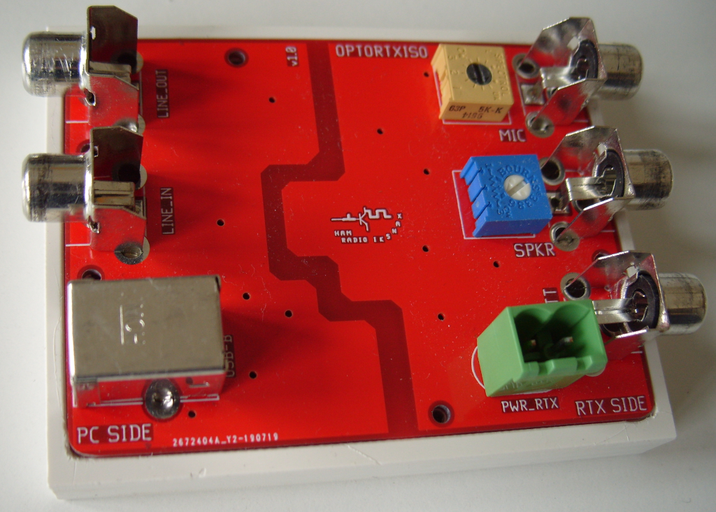
![[fig:board] Fully populated board](optortxiso_photo-1.png "fig:")
![[fig:board]
Fully populated board](optortxiso_photo-2.png "fig:")
The board is finished but some encolsure is recomended.
I’ve designed the pcb in such way that it can serve as a front pannel too. A milled housing is the way I choose; no mechanical drawing is really needed just the photo in figure should be enough. Refere to the pcb drawing for hole position and board outline.
![[fig:carter] Milled housing (could be
done better…)](optortxiso_photo-3.png "fig:")
![[fig:carter] Milled housing (could be
done better…)](optortxiso_photo-4.png "fig:")
First of all you have to build suitable cables between optortxiso, soundcard and RTX, simple and “universal” pin-jack connector are used for all connections, on the other side 3.5mm jack et similia will be needed.
Next derive RTX power supply to the terminal block (CONN4 in figure [3]) and get an USB-A to USB-B cable for PC power and PTT control.
Regulate both trimmer to minimum (full ccw) and fire up RTX and PC with the sw you already use. Than adjust levels and configure PTT as you did before using optortxiso, no more. When PTT will be active check for the red led. It may need to be changed PTT assignment: optortxiso use RTS.
Any comments, criticisms, suggests and maybe feedbacks are welcome!