![]()
![]()
Progress in yefa development: circular polarization and robust mechanic. Yefa performance mantained while obtaining circular polarization with single feed; a better mechanics ready for longer antennas
In 2018 I published the firsts results on yoctenna and yefa development and on Dubus 4/2019 a more accurate article has appeared. The conclusion of that publication indicated that I would devote myself to further developments in several directions: while the build of a longer antenna has been delayed I’ve reached two main goals. Here I’ll write about a way to obtain circular polarization in a very short yefa and how to build it in mechanically robust. Presently I’m working, too, for a deeper understanding of full-wave radiators and the “yocto” phenomen, but I’ll write of this in the (hope near) future.
Well, textboks give us at least three way to get circulary polarized emissions:
by using two crossed dipole
by axial helix
by using circularizator
Helix is incompatible with end-fire array, crossed dipole presents some problems (see below) and circularizator are proposed in textbooks often as curiosity; I’ve never seen one at frequency below some GHz.
The other question I faced off was if a perfect circular polarization is really needed for usual satellite traffic or if a sligthly elliptical one could be enough. Considering that many stations (amateur and profesional) use linear polarization even with not-sure-to-be-stabilized-satellites obtaining a -20...-30dB of signal attenuation when polarization completely mismatch, the loss of a few dB due to not perfectly circular polarization could be acceptable to work a complete pass owning some link budget margin.
Studying is the first step in finding a new solutions: and also to reviewing your documentation helps.
On an old issue (4/91) of VHF Communications, an interesting article by DL8ZX entitled Magnetically coupled Yagi antennas - ovelooked by Amateurs did give me an idea on how to feed yagi and yefa. Unfortunately I was not able to simulate the results claimed by the author but playing with this kind of feeder give me the opportunity to find a novel way to design yefa.
In very few words the idea presented by DL8ZX was to use a rectangular loop with the short side paralllel to dipoles and the long side along the boom to “magnetically” excite the yagi. This loop extends from DE to D1 approximatively. And according to the author this was employed in wide band TV reception yagi with good performance.
I’ve tried something similar and what I obtained is reported in figure [1]; forgot for a while the loop without the source, the vertical one. This way of feeding the yefa give almost the same results obtained with dipole or other structure I’ve investigated. The project reported in figure [1] has, however, some difference and improvements respect to the older 3 elements yefa I’ve described elsewhere.
After several simulated-only antennas I got a project worth
building: it’s derived from the 3
elements yefa432M3e-4 presented
in yoctenna
and yefa but with several difference, in addition to that of the
feeder.
The two dipole as D1 in yefa432M3e-4 has been
replaced by a nisl and RE has be done with a weird geometry a
bit difficult to build but that gives more F/B ratio; this was
the shape of the very first yoctenna I tested in 2018.
The obvious idea, at this point, was to add a second feeding loop rotated by 90 degrees along boom direction and to feed it in phase quadrature: the clasical way to get circular polarization. Mechanically it works: the two loops don’t interefere, clean as a couple of dipole in crossed-yagi.
Ok, it can work but... What if the second (let’s call it “the vertical one”) loop is not directly feeded but get some power by coupling with the first one (and this will be “the horizontal one”)? Two side of the feeding loops are parallel along the boom, so they couple: adjusting the distance between the two loops and the dimensions of the veritcal one I found it’s possible to get the right current flowing in it and in the right phase! This happen in a limitated bandwidth respect of that on which a similar yefa presents RL≤-17dB but also on the margins of the latter bandwidth polarization axial ratio remains decent.
The rest of a yefa with its loop elements supports circular polarization perfectly, so a circular (elliptical) polarized yefa has e minor increase in complexity.
With this considerations in mind and the early test performed it wasn’t that difficult to get a good result with few dozen simulations: this is the structure descripiotn.
	[comments]
	3 elements yefa for 432MHz with loop feed and cp

	[tags]
	v0.11

	[params]
	# TODO

	[etc]
	ek 0
	z0 200
	f0 430e6
	view_tetha 30.
	view_phi 45.
	view_zoom 2.


	[structure]
	# re
	nisl    0.0      0.000    0.0   3.12e-3 0.240 0.210 0.150 nnnn 0 11

	#de
	nisl    0.0      0.230    0.0        3.12e-3 0.240 0.200 0.200 nnnn 0 11
	looprect -0.000 +0.180 +0.070 rx 90.0 3.12e-3 120e-3 250e-3 1 50 15
	looprect +0.060 +0.180 -0.000 rx 90.0 ry 90.0 3.12e-3 120e-3 240e-3 0 0 15

	#d1
	nisl    0.0     0.350     0.0   3.12e-3 0.160 0.130 0.130 nnnn 0 11


	[excitation]
	src 1 1. 0.
	freq 370e6 470e6 10

	# Al wire (all made by 10x2mm)
	LD 5 0 0 0 3.5e7 0.0 0.0

	[pattern]
	standard
And here is the simulation results using 10x2mm alluminium strap, altough not significat difference are seen respect ideal conductors. Resistivity loss are not used in Tant and G/T calculations.
The term AXIAL in the following table is the axial
ratio (in dB) of elliptical polarization: 0dB mean perfectly
circular polarization, lower values means an oblong elliptical
polarization (new version of nec2op, see below,
indicate LIN when this value goes under -20dB).
	# freq         Zre      Zim    SWR    RL  Gtmax (tetha, phi)  Q    MQM   AXIAL   Tant  GT ( 60^)
	370000000   172.67    40.09  1.30 -17.76    6.79  90  90   ##     ##   -17.14  151.9  -15.02
	380000000   145.59   -26.56  1.42 -15.16    7.17  90  90   2.2    4.8  -10.79  116.8  -13.50
	390000000   137.34     2.43  1.46 -14.62    7.42  90  90   3.6    8.2   -9.09   85.2  -11.89
	400000000   159.24    29.43  1.32 -17.11    7.55  90  90   2.2    4.1   -6.99   61.7  -10.35
	410000000   190.25    37.34  1.22 -20.14    7.61  90  90   0.2    0.2   -4.26   47.8   -9.18
	420000000   212.77    30.60  1.17 -21.93    7.68  90  90   0.8    1.1   -2.00   41.1   -8.46
	430000000   223.55    19.78  1.16 -22.79    7.78  90  90   1.0    1.3   -0.49   38.7   -8.09
	440000000   224.67    10.23  1.13 -24.03    7.94  90  90   0.7    1.0   -0.61   39.3   -8.01
	450000000   220.64     4.28  1.11 -26.00    8.19  90  90   1.3    1.6   -1.35   44.0   -8.24
	460000000   205.94   -14.18  1.08 -28.44    8.28  90  90   ##     ##    -4.66   54.0   -9.04
One of the problems with the first yefa was the complex to build bulun. It’s a refined project but in addition to be difficult to build is also difficult to integrate in the antenna and make it waterproof.
For this test I decide to use a classical λ/2 balun made of coax cables. Doing this we lose the capability to fine tune impedance matching and every non-ideality in antenna end balun make return loss worst. However a good RL has bee achieved.
That’s not the final solution for this part and it’s not worth explaining better.
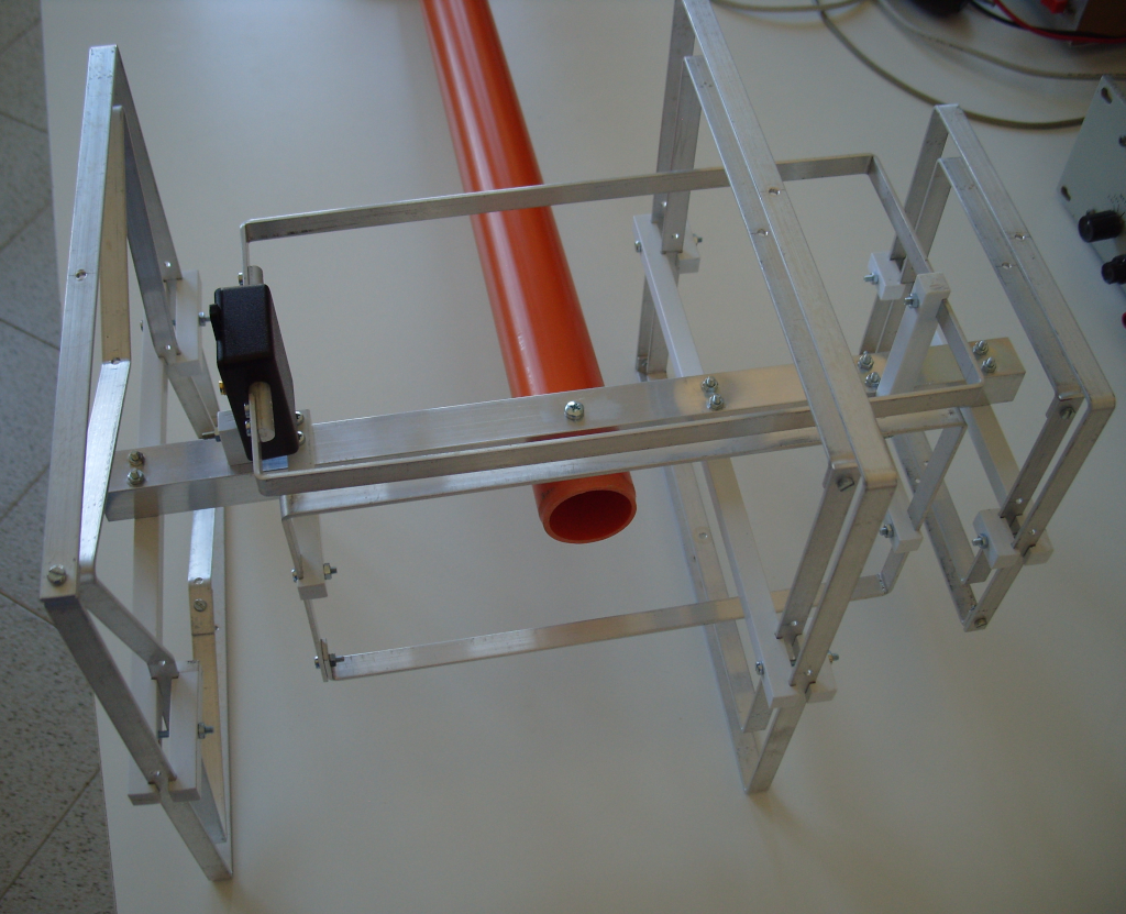
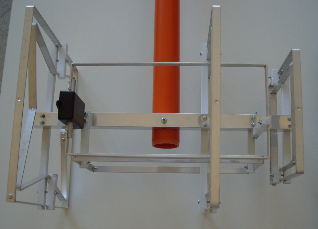
In the first yefa the boom was made by PVC drain pipes that exibits aging and some mechanical weakness during one year on the roof, as expected. This yefa has a metallic boom. So a different way for elements support is needed.
As shown in figure [2] and [3] the two loops of each elemet are tight together by three square section PVC rods; these rods are also connected to the boom using two M3 screw. In the future PVC will be substituted by a better plastic such as PP. The two screws (with the axis parallel to the boom) tight together the main (longer) rod with the others two. To be more robust these rods has cuts so that every straps enter 2mm inside the rods: rods are not weakened and fastening is not only due to pressure made by the screw. The better way to make these cut into the rods is to mill them but with a file good results can be obtained. For the RE the cuts are not orthogonal to the rods and require some attention.
The well know boom correction for yagi appear to be of no importance here: practical tests performed on the first yefa builded has shown that if boom is not close to the straps of the elements impedance does not changes. A separation of 2-3 times the boom cross dimension from the strap is enough.
I’ll not bother with precise mechanical drawings: figure [3], [4] and [2] give a resonable idea on how to build the antenna. The results are shown in photos in figure [3]. Screews and other particular are omitted, this realization is more complicated respect to a standard yagi but not difficult. Everything can be done with small workshop tools: the only demanding parts are the cuts in square section PVC used as supports, as said before. This project (as everything based on yoctenna concept) is not very sensitive to dimensions, tollerance can be quite high, one millimeter is not a problem.
Elements can be build bending the strap in bench vice, next you need a drill and a good ability to mark holes, bending point and dimensions, not more.
Coax to element connection has be done using a small pcb but this can lead to parassitic capacitance and other unideality that can compromise the whole project, so be carefull: a 0.5pF parassitic capacitance means something about -j700Ω in parallel to 200Ω antenna impedance and this can impact RL performance!
This test realization solved several problems but other remains open. Plane E and plane H beamwidth are almost equal, circular polarization has been obtained and with a simple feeding, bandwidth remain wide and it's easy to build.
But:
with this balun there’s no DC short; using a tapered line as in first yefa will solve this at the expense of a great complexity
it’s not possible to have linear polarization and circular too simply removing the vertical loop or opening it: the antenna must be changed in several dimension
this is just the core of a long antenna and the “long” part is the one that gives directivity and low side lobe and that has to be investigated and tested
theoretical understanding of how it works still lacks of a solid base
For all this unsolved problems more ideas are needed!
This antenna has been designed and build to verify several aspect, as pointed out up to now, and on the roof test has been very limitated. Once estimated that gain is not so different from what is aspected, RL is in good agreement (see the next figure) with simulations and circular polarization has been tested I havent’s spent more time. The antenna was on my roof for two weeks: I’ve heard several satellite beacon with very constant level during the whole passes, no fluctuation. I’ve had very few qso where 3-4dB less gain has been heard. Now is the time to build a longer circulary polarized yefa!
![[fig:meas20200226]yefa432M3e11 measurements (2020-02-260 in a
semi-outdoor location; spikes are due to interfeering
signal present at testing site](yefa432M3e11_meas_rl-20200226.png)
![[fig:meas20200226]yefa432M3e11 measurements
(2020-02-260 in a semi-outdoor location; spikes are due to
interfeering signal present at testing site](yefa432M3e11_meas_s11-20200226.png "fig:")
In first version of nec2g there was a stupid error
between radius and diameter: please update the code from the
repo.
Also nec2op
has been updated with circular polarization data and minor
stuff, get it
here .
Any comments, criticisms, suggests and maybe feedbacks are welcome!