![]()
![]()
In the last two years I've developed a radiator similar to a dipole and an end-fire array with only one driven element with interesting performances not only for bandwith in the classical sense but also for mantaining all performances over a large frequency range together with a high robustness aganist building imperfections
Everything was born in an attempt to build a simple antenna for 23cm band easy to feed using a classic 1:4 balun made by a lambda/2 coax. Base idea was a 1-lambda perimeter loop and the attempt to lower impedance to 200ohm started with putting another coax loop to get the same effect of the first director used in yagi antenna. Indeed, in addition to this other intersting characteristics came out: the first thing that struck me has been the frequency range upon which impedance remain nearly constant, so I went ahead...
The first project (2017-01-29) has been aimed to the desire of
understanding rather than a practical build.
Geometry was the result of several adjustment in cut-and-try
way with feeding on one side and an asymmetry needed to make
things working but results, shown in the following figures. speak
by themself.
The biggest doubt was if simulations was reliable: I was using nec2 in a condition known to give wrong results: 90 degrees bended conductors. So, after some day spent in simulation, the result has been a reduction of mechanical asymmetry which however did not produce satisfing results in radiation diagrams, while maintaining the other features of previous structure.
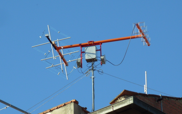
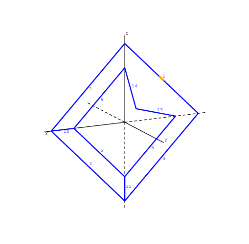
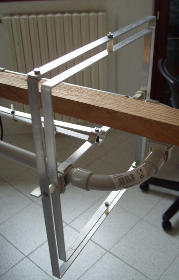
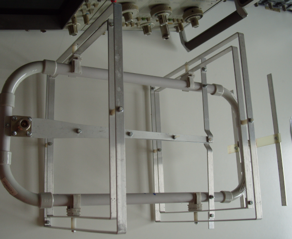
After other attempt the result has been a simmerical structure in both mechanics and radiation diagrams and the whole project (named yoctenna_1250MHz-1 finished 2017-07-09) is shown below along with a photo of the antenna builded.
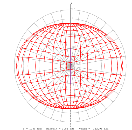
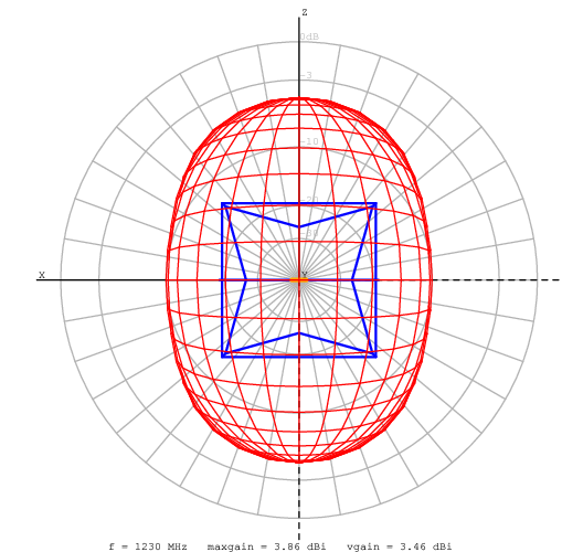
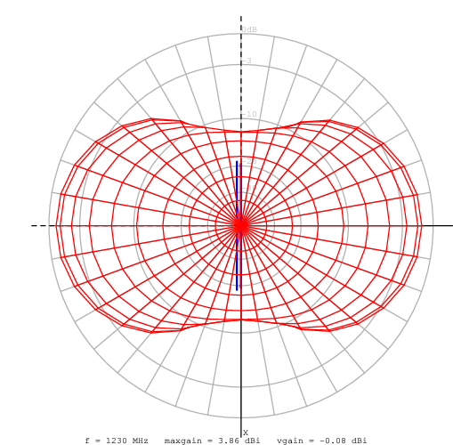
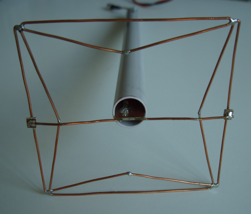

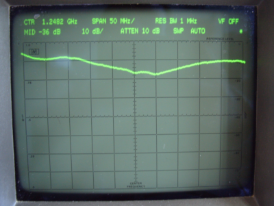
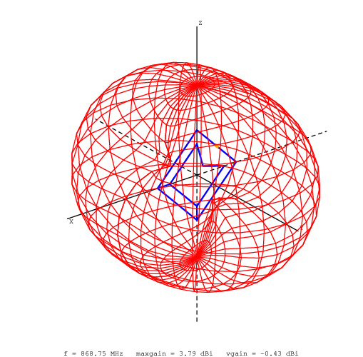
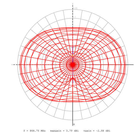
Its performance -measured in lab and not in an anechoic chamber-
hope that a more accurate build was in close agreement with
simulations.
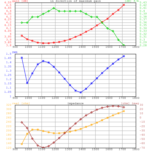
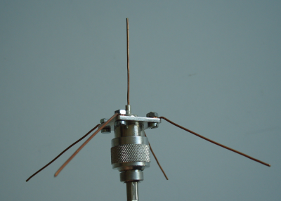
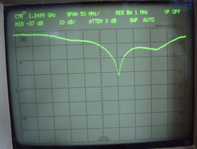
For comparison below is reported the frequency beheaviour of a
reference ground-plane cut on the same frequency.
The building of this laboratory prototype was particularly
difficult (mainly due to connection beetween inner and outer
loop on vertices) and mechanical issue arise.
Note that in this first build the purpose of having the feeding
directly on the loop has been abbandoned and the double loop has
become a sort of parassitic element of the driven dipole. Indeed
all features remained unchanged.
Simultaneously with this activity a large revisions of antenna books, paper an online resource has been done; moreover all papers pubblished on Dubus relative to directional antenna for space applications has been taken into consideration to understand the state of the art in last 10 years.
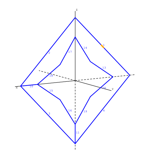
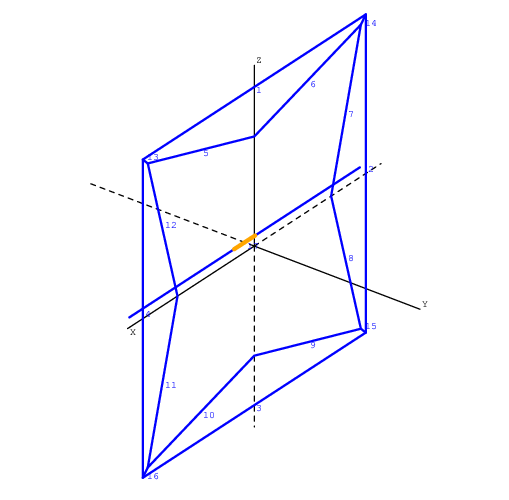
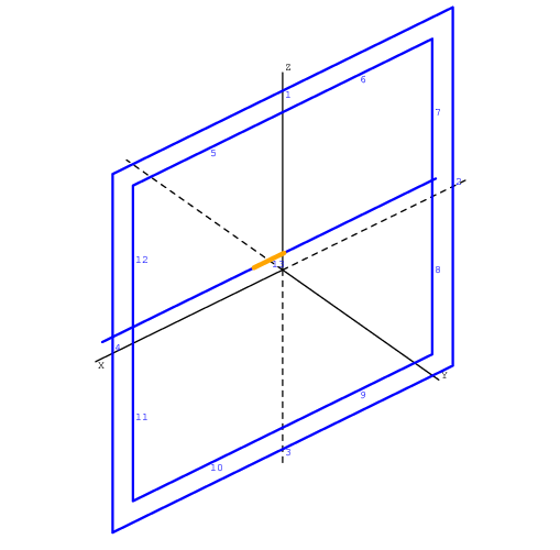
The first project of this radiator is shown in previous figure; nec2 model with GW cards (see below) has 8 principal vertices, I was working in temporary directories and I can't figure how to name this project. For a series of mental associations in those day come to me that yocto is the prefix for 1E-24 and came from "octo" that's eight. So the name "yoctenna" and than "yefa" that is for Yoctenna End Fire Array.
Going ahead with design I faced with direct usage of nec2 card in a so complex geometry: the single element composed of eight GW look like:
	GW 1 11 +0.045 +0 +0.045 -0.045 +0 +0.045 +0.0011
	GW 2 11 -0.045 +0 +0.045 -0.045 +0 -0.045 +0.0011
	GW 3 11 -0.045 +0 -0.045 +0.045 +0 -0.045 +0.0011
	GW 4 11 +0.045 +0 -0.045 +0.045 +0 +0.045 +0.0011
	GW 5 11 +0.043 +0 +0.043 +0 +0 +0.031 +0.0011
	GW 6 11 +0 +0 +0.031 -0.043 +0 +0.043 +0.0011
	GW 7 11 -0.043 +0 +0.043 -0.031 +0 +0 +0.0011
	GW 8 11 -0.031 +0 +0 -0.043 +0 -0.043 +0.0011
	GW 9 11 -0.043 +0 -0.043 +0 +0 -0.031 +0.0011
	GW 10 11 +0 +0 -0.031 +0.043 +0 -0.043 +0.0011
	GW 11 11 +0.043 +0 -0.043 +0.031 +0 +0 +0.0011
	GW 12 11 +0.031 +0 +0 +0.043 +0 +0.043 +0.0011
	GW 13 1 +0.045 +0 +0.045 +0.043 +0 +0.043 +0.0011
	GW 14 1 -0.045 +0 +0.045 -0.043 +0 +0.043 +0.0011
	GW 15 1 -0.045 +0 -0.045 -0.043 +0 -0.043 +0.0011
	GW 16 1 +0.045 +0 -0.045 +0.043 +0 -0.043 +0.0011
Alternig the size of one of the two loop by few millimeters just
to see how it works in a new simulation can take some time and
lead to oversights.
Therefore, both to speed up the study procedure but above
all to focus on understanding phenomena has been developed a
pre-processor for nec2 that accept a file that describe
macro-structures and generate a .nec file. The name of this
pre-processor is nec2g (nec2 file generator) and wait a file in
.n2s format (designed for the occasion) that look like this for
yoctenna_1250MHz-1:
	[comments]
	basic yoctenna (nisl+dipole)

	[tags]
	v0.1

	[etc]
	ek 0
	z0 200
	f0 1250e6
	view_tetha 30.
	view_phi 45.
	view_zoom 2.

	[structure]
	nisl 0.  0.0 0. 1.1e-3 0.090 0.086 0.062 yyyy 0 11
	dipole 0. -0.003 0. ax 1.1e-3 0.093 1 50 11

	[excitation]
	src 1 1. 0.
	freq 950e6 1750e6 20

	[pattern]
	standard
Noteworthy are the keywords in [structure] field (the rest of
.n2s file is quite intuitive): dipole is a single dipole in this
case placed in x=0.0, y=-0.003 and z=0.0 (unit of measure are
meters) and placed along x axis ("ax") its diameter is 1.1mm and
is 0.093m long, it's feeded at 50% of its length by source 1
(see field [escitation]), finally its segmentation is in 11 parts.
For what concern the double loop which underlies the idea of
yoctenna the keyword "nisl" is used, it's for nested
interconnectable square loop. nisl has the same parameters for
position and wire diameter, next follows the sizes of sides and
the distance between mean point of inner loop (parameter no more
used due to building difficulties). The four "yyyy" mean that
the four vertices are connected; the last two field mean that
the loop is not feeded and each side will be segmented in 11
parts.
(It's possible to rotate each element on each axis).
Using this format study, design and tune are much simpler,
faster and more understandable.
About the simulator -always having as a guideline to use only
free software (I mean the one according to gnu/gpl er similia)-
the only choice is nec2; in particular I've used nec2c version
by 5B4AZ.
Also for data visualization nec2 output is rather difficult to
understand and viewer like xnecview are not enough for all
purposes.
Therefore it has also been realized a post-processor called
nec2op mainly oriented to directional antennas for spatial
use: check repository for description.
These utility for nec2 are released under the term of gnu/gpl v3
or later license and ara available
on
gitlab.com/radioteknos/nec2g and
gitlab.com/radioteknos/nec2op or can be requested directly
from the author. They are written in python so can be executed
on a variety of operating system.
The developing activity of this antenna has required many tests and doing it in the 23cm band would have the advantage of being able to consider as substantially anechoic a fairly large local; but available equipement (and experience) was better for lower frequency so all the projects focused on 70cm band and finaly on 2m.
So to go beyond the experience gained with yoctenna_1250MHz-1 a similar antenna for 70cm band has been designed. Meanwhile some familiarity with the structure had been acquired, its behavior based on dimension and current distribution thanks also to the capability of xnecview.
Simulation of this new antenna, described by the following n2s file:
	[comments]
	basic yoctenna (nisl+dipole) for 432MHz using 10x2mm Al (eq. dia 6.23mm)
	[tags]
	v1.0

	[etc]
	ek 0
	z0 200
	f0 430e6
	view_tetha 30.
	view_phi 45.
	view_zoom 2.

	[structure]
	nisl 0.  0.0 0. 6.23e-3 0.250 0.220 0.220 nnnn 0 11
	dipole 0. -0.012 0. ax 6.23e-3 0.245 1 50 11

	[excitation]
	src 1 1. 0.
	freq 350e6 550e6 20

	[pattern]
	standard
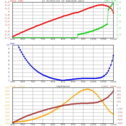
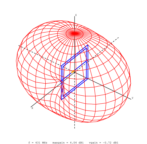
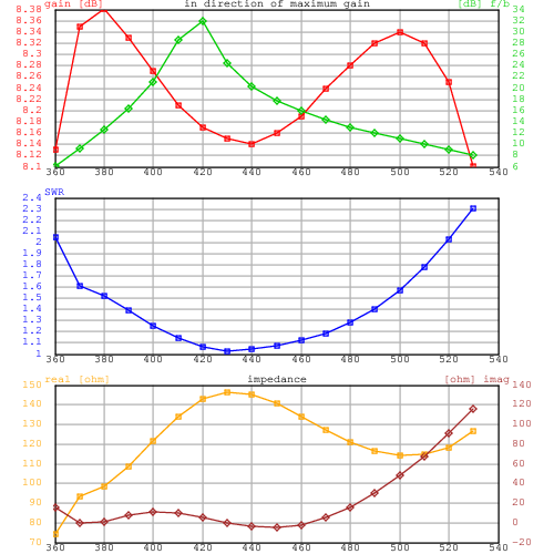
shows surprising results after nec2op post-processing:
	# freq         Zre      Zim    SWR    RL  Gtmax (tetha, phi)  Q   MQM     Tant  GT (  0^) Tant  GT ( 30^)
	350000000    53.34    41.21  3.92  -4.53    4.76  90 270   ##     ##   230.9  -18.87   218.3  -18.63
	360000000    98.60    60.08  2.26  -8.25    4.43  90 270   2.0   14.0 226.1  -19.11   214.1  -18.88
	370000000   141.19    59.21  1.64 -12.36    4.27  90 270   0.8    2.4 221.8  -19.19   210.1  -18.95
	380000000   172.33    45.40  1.33 -16.97    4.17  90 270   1.6    3.0 217.8  -19.21   206.5  -18.98
	390000000   190.36    28.04  1.16 -22.41    4.12  90 270   1.6    2.2 214.2  -19.19   203.2  -18.96
	400000000   198.89    13.17  1.07 -29.60    4.08  90 270   1.3    1.4 210.9  -19.16   200.1  -18.93
	410000000   202.25     2.73  1.02 -41.12    4.06  90 270   0.8    0.9 207.8  -19.12   197.3  -18.89
	420000000   203.50    -3.59  1.03 -38.11    4.05  90 270   0.5    0.5 205.0  -19.07   194.7  -18.84
	430000000   204.35    -6.78  1.04 -34.02    4.04  90 270   0.2    0.2 202.4  -19.02   192.2  -18.80
	440000000   205.64    -7.81  1.05 -32.49    4.05  90 270   0.0    0.0 200.0  -18.96   190.0  -18.74
	450000000   207.71    -7.48  1.05 -31.58    4.06  90 270   0.1    0.1 197.8  -18.90   187.9  -18.68
	460000000   210.67    -6.40  1.06 -30.37    4.07  90 270   0.2    0.2 195.8  -18.85   185.9  -18.62
	470000000   214.51    -5.01  1.08 -28.63    4.09  90 270   0.2    0.2 193.9  -18.79   184.1  -18.56
	480000000   219.14    -3.62  1.10 -26.66    4.11  90 270   0.1    0.2 192.1  -18.73   182.4  -18.50
	490000000   224.46    -2.50  1.12 -24.74    4.13  90 270   0.1    0.1 190.5  -18.67   180.8  -18.44
	500000000   230.36    -1.82  1.15 -23.02    4.16  90 270   0.0    0.1 189.0  -18.60   179.3  -18.38
	510000000   236.69    -1.73  1.18 -21.50    4.19  90 270   0.0    0.0 187.6  -18.54   177.9  -18.31
	520000000   243.33    -2.33  1.22 -20.19    4.22  90 270   0.1    0.2 186.2  -18.48   176.5  -18.25
	530000000   250.13    -3.69  1.25 -19.04    4.25  90 270   0.2    0.3 185.0  -18.42   175.3  -18.19
	540000000   256.94    -5.85  1.29 -18.04    4.29  90 270   ##     ##   183.9  -18.36   174.1  -18.12
Accepting a Return Loss of -17dB (SWR &le 1.3:1) the antenna can be used from 380MHz up to over 540MHz with almost constant performance. In the graph below it is seen the behavior of immaginary part of the impedance who has an inflaction of considerable extension while real part remain arround 200ohm for a similar extension!
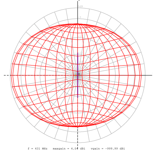
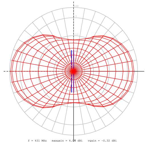
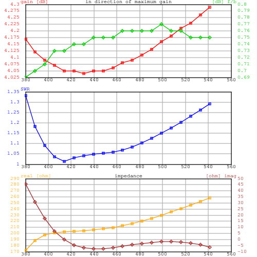
This can be both a validation of the model and the idea, both in qualitative and quantitative terms. Also take into account that tests are carried in a 12m2 room with this yoctenna placed on a wooden easel at about 1.2m over the floor. Points where RL is less than -20dB are very much affected by the position inside the room, points above not. As soon as possible measures will be taken in an anechoic chamber, although there are no big differences to be expected.
A little note about building: instead of using classic round pipe or circular section rod I prefered to use 10x2mm slab that;s easy to bend. nec2 consider only round section wire, so equivalent diameter are used as reported in K3WQ paper (se bibliography) giving a great accuracy.
At this point in the experimentation it was clear that a similar
radiator presented innovative features and maybe interesting
uses.
But the major curiosity was, however, that about the possibility
of using it in an end-fire array with just one driven element,
i.e. something conceptually similar to a yagi.
So yoctenna developing has been interrupted in favor of that of
yefa: yoctenna end fire array.
One last note before switching to yefa.
If making an high performance antenna can be challenging, feed
it is certainly more difficult.
Yoctenna, I remember, born (by mistake?) wanting to get a simple
antenna with 200ohm at feed point so to be feeded by a simple
lambda/2 balun.
But now that balun would no longer have the necessary bandwidth.
So one of the problems that got in the way in the yoctenna first
and yefa than building was just to find a suitable way to design
a wide band balun.
The idea came from a thesis (see the appendix) which resumed a
method found on several text book: Krasus "Antennas" as an
example (again in the appendix).
In Vinayagamoorthy thesis, however, the way is a tapering on
printed circuit board that require tracks of few tenths of
millimeter: unsuitable for even small power.
Therefore a wide band tridimensional balun has been realized
which took a long time and which does not deserve to be
described here. It will be part of another pubblication although
the latest developments lead to abandoning this solution in
favor of more practical, simple, efficient and elegant ones.
The yoctenna described above no longer exists: two copies had been made to test with double antenna method. Again inside the lab and not in an anechoic chamber the result of this test was within ^plusmn 1dB from the expected.
The two elements making up this yoctenna were immediately exploited to build a three element yefa: modifying the dipole and exploiting the two nisl (see nec2g paragraph) the driven element and the reflector have been realized. For the first director initial attempt to use another nisl was unsuccesfull: the risult of simulation were very bad. I still didn't understand how to size and place this new type of element.
When you want to design a yagi it's natural to start with well
known project developed by the many who have ventured into this
work in the last few decades: I would do someone wrong if I
tried to mention only the part that comes to mind.
The problem is that projects, such rules for yagi dipole length
tapering and posistion distribution along the boom have not
given (so far) the remarkable results found for yagis.
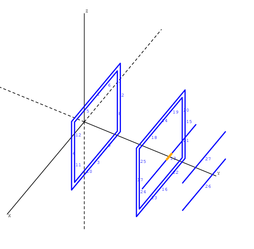
Therefore the first yefa was born with a double dipole as first director, here is the project, simulation and measurement for the one who took the name of yefa432M3e-4.
	[comments]
	3 elements yefa for 432MHz

	[tags]
	v0.2

	[etc]
	ek 0
	z0 150
	f0 430e6
	view_tetha 30.
	view_phi 45.
	view_zoom 2.


	[structure]
	# re
	nisl    0.0     0.035    0.0        6.23e-3 0.250 0.220 0.220 nnnn 0 11

	#de
	dipole  0.0    +0.255    0.0     ax 6.23e-3 0.275 1 50 11
	nisl    0.0     0.23     0.0        6.23e-3 0.250 0.220 0.220 nnnn 0 11

	#d1
	dipole   0.0   +0.360  -0.050   ax 6.23e-3 0.220 0 0 11
	dipole   0.0   +0.360  +0.050   ax 6.23e-3 0.220 0 0 11


	[excitation]
	src 1 1. 0.
	freq 350e6 550e6 20

	[pattern]
	standard
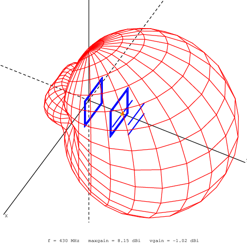
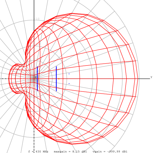
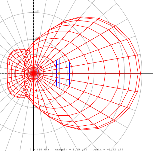
Also for this project a wide band balun has been used like the one mentioned above; this structure work both as balun and as an impedance matching network giving an even larger bandwidth and a better RL. Here characteristic impedance of the antenna is 150ohm and a matching better than -17dB is in the range from 400MHz to 480MHz: obviously we have a reduction in bandwidth but gain and pattern cleanness are mantained over all the bandwidth (some can be said for antenna temperatura even if this is not a relevant parameter for a so modest dimension antenna).
	# freq         Zre      Zim    SWR    RL  Gtmax (tetha, phi)  Q   MQM     Tant  GT (  0^) Tant  GT ( 30^)
	350000000    15.70    -5.54  9.57  -1.82    7.44  90  90   ##     ##   238.9  -16.34   180.2  -15.12
	360000000    74.31    15.99  2.05  -9.27    8.13  90  90   0.9    5.0 233.1  -15.55   140.9  -13.36
	370000000    93.23    -0.82  1.61 -12.64    8.35  90  90   1.6    4.6 227.9  -15.23   119.1  -12.41
	380000000    98.56     1.00  1.52 -13.68    8.38  90  90   0.8    1.9 223.3  -15.11   108.2  -11.96
	390000000   108.56     7.29  1.39 -15.77    8.33  90  90   0.9    1.9 219.1  -15.08   103.0  -11.80
	400000000   121.42    10.97  1.25 -18.96    8.27  90  90   0.3    0.5 215.4  -15.06   100.4  -11.75
	410000000   133.79    10.21  1.14 -23.42    8.21  90  90   0.4    0.5 212.1  -15.06    99.1  -11.75
	420000000   142.69     5.81  1.07 -29.92    8.17  90  90   0.7    0.8 209.1  -15.03    98.4  -11.76
	430000000   146.49     0.12  1.02 -38.53    8.15  90  90   0.7    0.8 206.5  -15.00    97.9  -11.76
	440000000   145.31    -4.20  1.04 -33.42    8.14  90  90   0.4    0.4 204.1  -14.96    97.6  -11.75
	450000000   140.52    -5.23  1.08 -28.57    8.16  90  90   0.2    0.2 201.9  -14.89    97.3  -11.72
	460000000   133.92    -2.16  1.12 -24.86    8.19  90  90   0.9    1.1 200.0  -14.82    97.2  -11.69
	470000000   127.04     5.04  1.19 -21.43    8.24  90  90   1.7    2.4 198.2  -14.73    97.5  -11.65
	480000000   120.98    16.01  1.28 -18.27    8.28  90  90   2.6    4.3 196.7  -14.66    98.2  -11.64
	490000000   116.51    30.33  1.41 -15.47    8.32  90  90   3.4    7.2 195.2  -14.58    99.5  -11.66
	500000000   114.20    47.68  1.57 -13.07    8.34  90  90   4.3   11.7 193.9  -14.53   101.9  -11.74
	510000000   114.60    67.87  1.78 -11.05    8.32  90  90   5.0   18.7 192.6  -14.53   105.6  -11.91
	520000000   118.40    90.78  2.03  -9.39    8.25  90  90   5.6   29.4 191.3  -14.57   110.8  -12.20
	530000000   126.58   116.28  2.31  -8.06    8.10  90  90   5.9   44.1 190.0  -14.69   117.9  -12.62
	540000000   140.53   143.98  2.60  -7.03    7.85  90  90   ##     ##   188.5  -14.90   126.8  -13.18
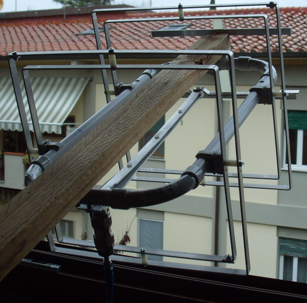
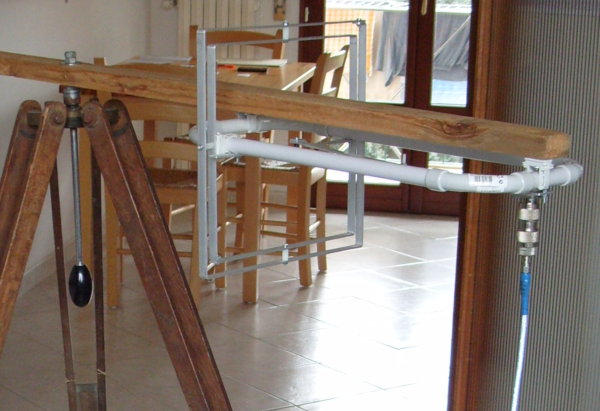
Yefa shown just outside the windows has been used for a quick test on the air as uplink antenna on linear transponder of one of XW-2* satellite with great result, how little this test can be worth.
After this antenna various other larger ones were designed in an attempt to be able to compare it with those of similar length that can be found in the table maintained by VE7BQH ; their implementation has, however, presented many problems and has been abandoned in favor of smaller antenna as described in the following paragraph.
Since my IK5NAX station had been reduced at a small antenna park for many years, yefa study was domesticated to restart the VHF/UHF satellite station as well as for other activities in the same bands. Therefore, after the restoration of rotor system and some construction work, the study was addressed to antennas whose length is about 1m for 2m and 70cm band in order to verify electric and mechanical ideas in view of more demanding achievements.
For 70cm band, after many calculations, tests and simulations, the
project more suitable to be made reliably and able to verify
many radioelectric and mechanical aspects has been that of a
yefa similar to the previous one (yefa432M3e-4) but with five
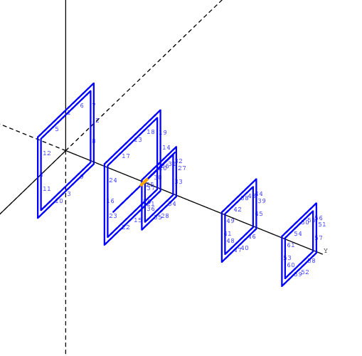
elements for a total length of 700mm: exactly one lambda.
It is still an'antenna with a dipole as driven element and a
nisl as parasitic of dipole, as can be seen in the following
files.
	[comments]
	5 elements yefa for 432MHz

	[tags]
	v0.1

	[etc]
	ek 0
	z0 100
	f0 430e6
	view_tetha 0.
	view_phi 90.
	view_zoom 2.

	[structure]
	# re
	nisl    0.0     0.000     0.0        6.23e-3 0.260 0.230 0.230 nnnn 0 11

	#de
	nisl    0.0     0.200     0.0        6.23e-3 0.260 0.230 0.230 nnnn 0 11
	dipole  0.0     0.235     0.0     ax 6.23e-3 0.287 1 50 11

	#d1
	nisl    0.0     0.280     0.0        6.23e-3 0.160 0.130 0.130 nnnn 0 11

	#d2
	nisl    0.0     0.520     0.0        6.23e-3 0.160 0.130 0.130 nnnn 0 11

	#d3
	nisl    0.0     0.700     0.0        6.23e-3 0.160 0.130 0.130 nnnn 0 11

	[excitation]
	src 1 1. 0.
	freq 380e6 480e6 10

	[pattern]
	standard
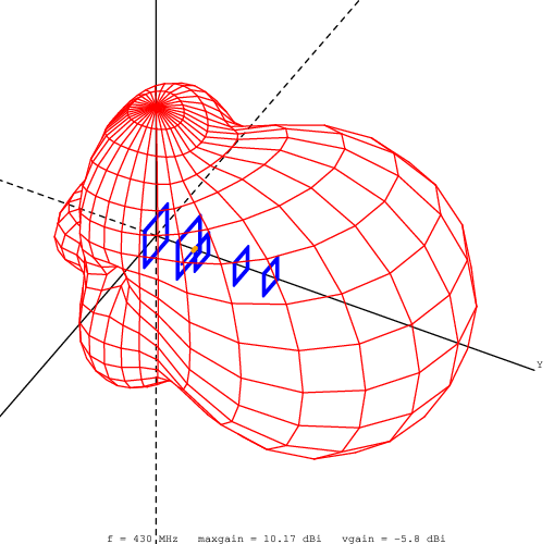
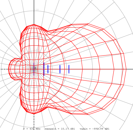
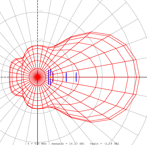
Simulations results, shown below, inevitably show that acceptable
performances are achievable on an even restricted bandwith as the
total lenght increase but F/B, Tant and in more general
sense the cleannes of secondary lobes is mantained over a
frequency range always greather than that of a yagi.
	# freq         Zre      Zim    SWR    RL  Gtmax (tetha, phi)  Q   MQM     Tant  GT (  0^) Tant  GT ( 30^)
	380000000    65.56    -6.52  1.54 -13.49    9.42  90  90   ##     ##   225.7  -14.12    95.3  -10.37
	390000000    79.51     1.52  1.26 -18.83    9.47  90  90   1.2    2.0 221.9  -13.99    92.5  -10.19
	400000000    92.78     3.36  1.09 -27.68    9.56  90  90   0.1    0.1 218.5  -13.83    90.4  -10.00
	410000000   101.18     0.44  1.01 -44.06    9.70  90  90   0.7    0.7 215.6  -13.64    88.5   -9.77
	420000000   102.94    -2.94  1.04 -33.76    9.90  90  90   0.4    0.4 213.1  -13.39    86.6   -9.47
	430000000   100.13    -3.11  1.03 -36.17   10.17  90  90   0.3    0.4 211.1  -13.07    84.4   -9.10
	440000000    96.28     0.04  1.04 -34.44   10.51  90  90   0.6    0.7 209.4  -12.70    82.2   -8.64
	450000000    92.33     2.24  1.09 -27.63   10.95  90  90   0.2    0.2 208.2  -12.24    79.5   -8.06
	460000000    77.44    -1.52  1.29 -17.90   11.54  90  90   2.6    4.6 207.3  -11.63    76.2   -7.28
	470000000    33.70    16.64  3.06  -5.89   12.38  90  90   ##     ##   206.3  -10.76    74.7   -6.35
From the analysis of the structure we see -and performing many simulations this is even more evident- how the dimensions are not critical at all so much so that in this project only two set of dimensions are used.
Measurement on an antenna larger than previous one and without wanting to use an anechoic chamber was rather approximate and don't worth to be reported (also because I forgot to take a picture...): qualitatively it shows the same good agreement with simulation for the previous 432MHz yefa shown above.
For 2m band has been build a even more modest antenna: only 0.5
lambda. However, just as the yefa432M5e-1 was designed to give
maximum performance in 432-435MHz segment but be usable also in
400-402MHz band, this one want to be used in wheather satellite
band arround 137MHz.
But ultimately this antenna had three purposes:
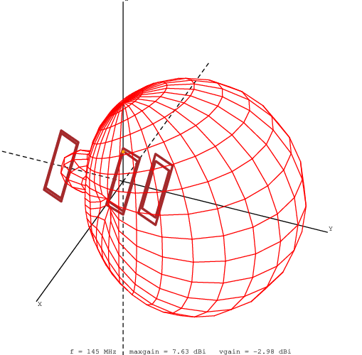
Follows the presentation of the project and the simulations results.
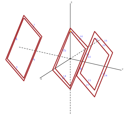
	[comments]
	same as yefa144M3e-3 but with insulated wire (d=1.76, D=3.5mm
	er=3.3, so d=1.65 and L=100nH/m)

	[tags]
	v0.3a

	[etc]
	ek 0
	z0 100
	f0 145e6
	view_tetha 0.
	view_phi 90.
	view_zoom 2.


	[structure]
	# re
	cfnrl 0.0 -0.650 0.0 insu 2e-3 3.2  1e-3  2.20  1.0  2.40  1.0  0.015  0 15

	# de
	cfnrl 0.0  0.0  0.0  insu 2e-3 3.2  1e-3  2.02  1.0  2.30  1.05  0.015  1 15

	# d1
	cfnrl 0.0 0.340 0.0 insu 2e-3 3.2  1e-3  1.90  1.0  2.40  1.0  0.015  0 15

	[excitation]
	src 1 1. 0.
	freq 135e6 155e6 10

	[pattern]
	standard
A further complication of this antenna concern the realization with common electric system insulated wire: without going into details, since nec2 does not provide dielectric mode, a simple correction based on wire loading with lumped R, L, C has been applied together with a wire diameter correction; results are in very well agree with measurements.
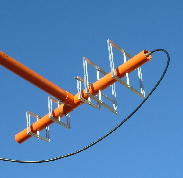
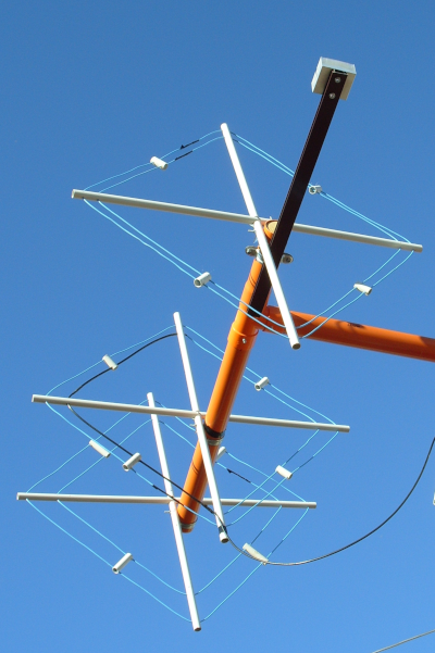
As can be seen in the previus listing in this antenna there is no more dipole but a new element called cfnrl (center feed nested rhombic loop) is used; it has an auto-balun or natural balun. In practice, as can be seen from the first photo below, coax outer conductor starts at the lowest point of the loop and continue up to the higher one; here the coax ends and the other half of the loop is made by common wire. So loop feeding occurs in correspondence of the highest point and due to simmetry the bottom vertex has a null potential so it's safe to make the coax exit from there. In fact the coax is divided into two pieces: from top vertex starts 410mm of RG59 (75ohm) making an impedance match between 100ohm of the antenna to the 50ohm of the system and the coax below (RG58). I've to put back the material related to this project and as soon as possible I'll show more details, that's one of the aspects I'm working on.
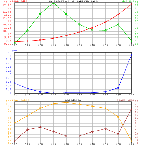
	# freq         Zre      Zim    SWR    RL  Gtmax (tetha, phi)  Q   MQM     Tant  GT (  0^) Tant  GT ( 30^)
	135000000    65.39   -68.66  2.50  -7.34    6.25  90  90   ##     ##   744.6  -22.47   613.8  -21.63
	137000000    73.05   -45.49  1.84 -10.59    6.73  90  90  10.3   41.6 723.3  -21.86   552.7  -20.69
	139000000    84.92   -24.99  1.37 -16.11    7.03  90  90   7.1   14.1 702.8  -21.44   505.6  -20.01
	141000000    98.47   -11.07  1.12 -25.00    7.22  90  90   3.7    4.7 683.8  -21.13   470.7  -19.51
	143000000   107.61    -5.01  1.09 -27.15    7.41  90  90   1.6    1.9 666.8  -20.83   444.4  -19.07
	145000000   106.11    -1.96  1.06 -30.14    7.63  90  90   2.1    2.4 652.4  -20.51   423.5  -18.64
	147000000    93.88     6.77  1.10 -26.55    7.91  90  90   5.7    7.0 640.2  -20.15   406.1  -18.18
	149000000    76.92    26.42  1.49 -14.15    8.24  90  90  12.2   29.2 630.3  -19.76   392.7  -17.70
	151000000    61.36    56.80  2.34  -7.92    8.55  90  90  20.9   163.1 621.4  -19.38   387.5  -17.33
	153000000    50.63    95.59  4.04  -4.39    8.67  90  90   ##     ##   610.9  -19.19   399.0  -17.34
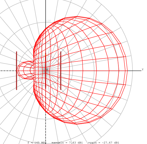

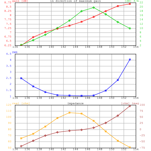
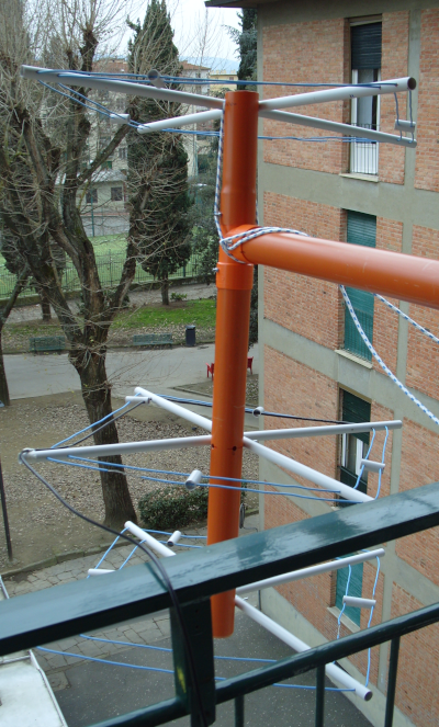
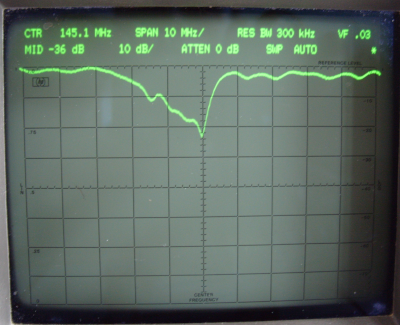
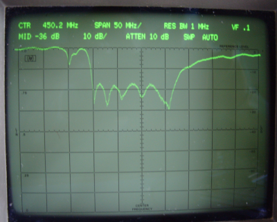
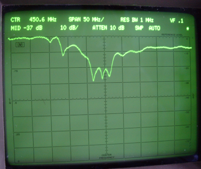
Needless to say, in this case more than ever the measurements were very difficult and potentially affected by severe errors. Despite this the last image appears a quit good measurement of RL taken with the antenna just protruding from the terrace pointing down, the terrain is about 10m below. There is only one shift in frequency of some MHz to lower frequency probabily due to a longer cut in wire (is not easy to tension wire with a so light support).
Despite a theoretical analysis was not made (my applied elctromagnetism knoledge are a bit rusty...) seem to understand at least this:
More to test these ideas on 23cm band next steps would be:
I've developed this antenna in extreme loneliness mainly because I didn't believe to what I saw and I wanted to have tangible evidence. For a few days my satellite station for VHF/UHF is operational again after more then 10 years of inactivity witth the two yefa visible in the opening photo.
I would like to propose it as an innovative way in the design of
directional antennas a and I will be grateful to anyone would
send me comment, criticism, suggests and maybe feedback after
reproduction of these projects.
For my part I will dedicate myself to on air test, instrumental
verifications to enlarge knowledge on this idea to understand if
it can really be interesting from a technological point of view.
I wrote this page very quickly and therefore it is likely that there are errors, oversights, lightnesses and shortcomings: please let me know and ask me for explanations and missing or unclear information.
All the material contained in this paper, the idea and the
project here exposed with the names of yoctenna and yefa, as
well as the names themselves, are released under the terms of
CERN Open Hardware License or under GNU/GPL License v3 or newer,
depending on the relevance of the material.
The autor is:
Lapo Pieri
via delle Ortensie, 22
50142 FIRENZE
![]()
![]()
www.radioteknos.it/ik5nax_en.html
T. +39 055 706881 - +39 329 2599801