![]()
![]()
After developing antennas based on the concept I've called "yocto" (see the first article YOCTENNA and YEFA) I thought the dipole too, and not just the rectangular loop, could also be widen in bandwidth while maintaining performance. The yodip or yocted dipole was born. The first tests has given good results but since a dipole as is often is not very useful I ventured into a more complex antenna useful also for operational needed: a SatNOGS station.
The yodip from yocted dipole is simply a dipole to which they have been joined two other dipoles of slight different dimension. In yoctenna is possible to put a second loop concentric to the first to obtain effects described in YOCTENNA and YEFA, for the dipole two other elements are needed to avoid losing omniderctionality.
A complete analysis and e design method for this structure has not yet completed. In the following you can find the results of some simulations which shown the potential of this configuration.
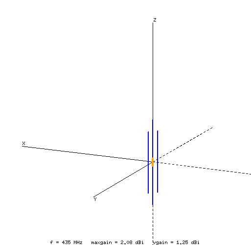
The structure is show in the figure below and the trend of parameters can be seen both from graphs but better from the table: a dipole build with 10x2mm strap is matched on 400MHz to 470MHz band! The gain don't vary over the bandwidth, neither the radiation pattern.
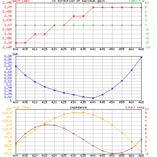
# freq         Zre      Zim    SWR    RL    Gtmax    Q      MQM
 400000000    93.03     1.62  1.22 -20.24    2.05    ##     ##
 405000000    97.87     4.01  1.16 -22.59    2.05    0.8    1.1
 410000000   102.37     5.53  1.12 -25.10    2.06    0.5    0.6
 415000000   106.33     6.20  1.09 -27.64    2.06    0.1    0.2
 420000000   109.55     6.08  1.06 -30.06    2.07    0.1    0.2
 425000000   111.84     5.29  1.05 -32.36    2.07    0.4    0.4
 430000000   113.03     4.02  1.04 -35.00    2.08    0.5    0.6
 435000000   112.99     2.49  1.02 -39.16    2.08    0.6    0.6
 440000000   111.66     0.97  1.01 -42.65    2.09    0.5    0.6
 445000000   109.05    -0.24  1.04 -34.98    2.09    0.4    0.4
 450000000   105.27    -0.89  1.07 -28.96    2.09    0.1    0.1
 455000000   100.48    -0.74  1.12 -24.62    2.09    0.3    0.4
 460000000    94.88     0.37  1.19 -21.19    2.09    0.8    1.2
 465000000    88.70     2.54  1.28 -18.33    2.09    ##     ##
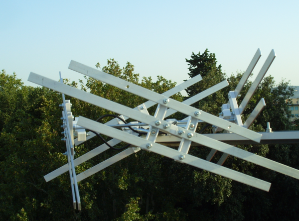
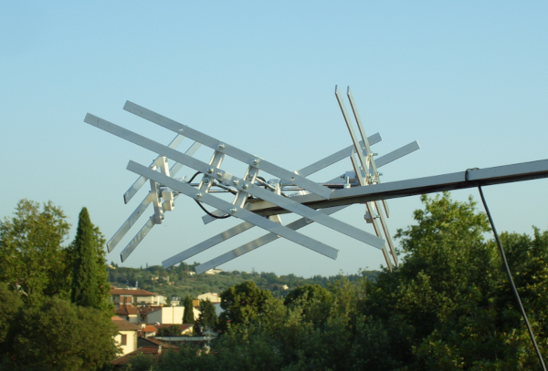
Lindenblad antenna is well known and I'll not spend words
here. The news was that of using the dipole described before.
The description of the structure is based on .n2s
file already introduced for the other antennas.
Basically there are four dipole on a circle of about 0.3λ
tilted by 30°.
[comments]
yocted lindenblad antenna (yolinda)

[tags]
v1.0

[etc]
ek 0
z0 113
f0 435e6
view_tetha 30.
view_phi 45.
view_zoom 2.


[structure]
dipole 0.110 0.000  0.000 ay rx 30.0 6.23e-3 0.330 1 50 15
dipole 0.110 0.000 +0.030 ay rx 30.0 6.23e-3 0.230 0 0 15
dipole 0.110 0.000 -0.030 ay rx 30.0 6.23e-3 0.230 0 0 15

dipole -0.110 0.000  0.000 ay rx -30.0 6.23e-3 0.330 2 50 15
dipole -0.110 0.000 +0.030 ay rx -30.0 6.23e-3 0.230 0 0 15
dipole -0.110 0.000 -0.030 ay rx -30.0 6.23e-3 0.230 0 0 15

dipole 0.000 0.110  0.000 ax ry 30.0 6.23e-3 0.330 3 50 15
dipole 0.000 0.110 +0.030 ax ry 30.0 6.23e-3 0.230 0 0 15
dipole 0.000 0.110 -0.030 ax ry 30.0 6.23e-3 0.230 0 0 15

dipole 0.000 -0.110  0.000 ax ry -30.0 6.23e-3 0.330 4 50 15
dipole 0.000 -0.110 +0.030 ax ry -30.0 6.23e-3 0.230 0 0 15
dipole 0.000 -0.110 -0.030 ax ry -30.0 6.23e-3 0.230 0 0 15

dipole 0.000 0.000 0.000 ax 6.23e-3 0.210 0 0 15
dipole 0.000 0.000 0.000 ay 6.23e-3 0.210 0 0 15
dipole 0.12374 0.12374 0.000 ay rz 45.0 6.23e-3 0.350 0 0 15

dipole 0.24749 0.24749 -0.400 az 6.23e-3 0.800 0 0 15


[excitation]
src 1 +1. 0.
src 2 -1. 0.
src 3 -1. 0.
src 4 +1. 0.
freq 395e6 470e6 15

[pattern]
standard
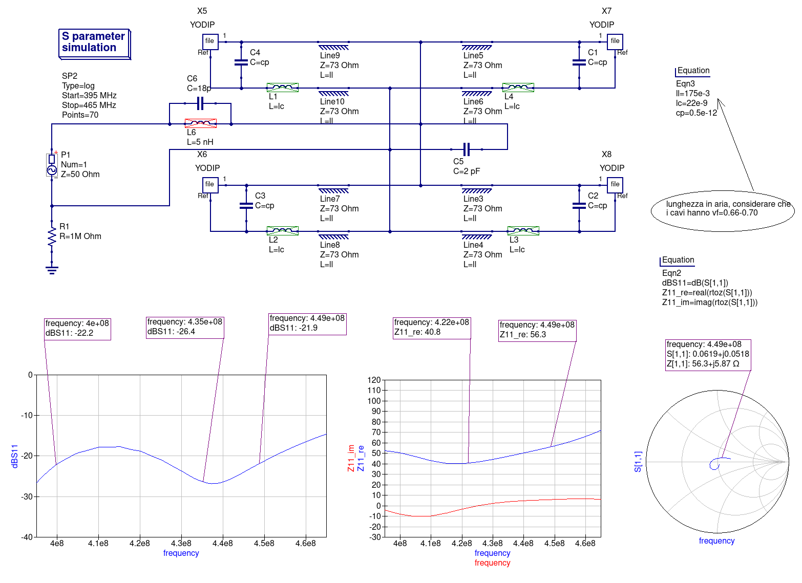
Dipole feeding must be in phase and of equal amplitude. Each dipole, as can be seen from simulation results shown in the previous paragraph, has an impedance with a large reactive component. After some circuit simulation has been possible to obtain a very good matching on the whole bandwidth (approx 400MHz to 460MHz) simply connecting each half-dipole by the means of a piece of 75Ω coaxial cable of about λ/4 in length, as can be seen from schematics below. In that simulation the inevitable parasitics from interconnections has been taken into account, too. Obviously then there is the problem of balanced to unbalanced transition and for this a bazooka-lime was used, giving excellent results.
As anticipated in the previous paragraph yolinda has an impedance, for each dipole, non matched to 50Ω and with a large reactive component. From the following table it can be seen, however, the all the other parameters are constant over a bandwidth of about 70MHz around 70cm band center frequency.
# freq         Zre      Zim    SWR    RL  Gtmax (tetha, phi)   AGT  (%%)  Q    MQM   AXIAL   Tant  GT ( 30^)
 395000000    91.84   -36.75  1.51 -13.82    1.94 100 330  0.999 -0.1  ##     ##    -1.78  196.0  -20.98
 400000000   100.78   -33.83  1.40 -15.59    1.99 100 320  0.999 -0.1  0.8    1.7   -2.07  194.9  -20.91
 405000000   111.82   -33.53  1.35 -16.62    2.05 100 320  0.999 -0.1  0.7    1.4   -2.19  193.6  -20.82
 410000000   123.56   -38.77  1.40 -15.51    2.07 100 320  0.999 -0.1  2.7    5.6   -2.24  192.1  -20.77
 415000000   130.53   -50.33  1.55 -13.38    2.04 110 310  0.999 -0.1  3.6    9.5   -2.77  190.4  -20.76
 420000000   128.96   -62.00  1.69 -11.82    2.00 110 310  0.999 -0.1  2.8    9.1   -2.50  188.7  -20.76
 425000000   123.12   -68.55  1.78 -11.00    1.93 110 310  0.999 -0.1  1.3    4.8   -2.21  187.1  -20.79
 430000000   117.38   -71.03  1.84 -10.60    1.88 100 120  0.999 -0.1  0.2    1.0   -0.61  185.7  -20.81
 435000000   112.75   -71.57  1.87 -10.39    1.85 100 120  0.999 -0.1  0.3    1.1   -0.60  184.6  -20.81
 440000000   109.14   -71.31  1.88 -10.28    1.83 100 120  0.999 -0.1  0.4    1.9   -0.60  183.7  -20.81
 445000000   106.23   -71.05  1.90 -10.18    1.82 100 120  0.998 -0.2  0.4    1.6   -0.53  182.9  -20.80
 450000000   103.34   -71.13  1.92 -10.03    1.82 110 130  0.998 -0.2  0.3    1.3   -1.07  182.0  -20.78
 455000000    99.97   -71.29  1.95  -9.82    1.81 110 130  0.998 -0.2  0.3    1.6   -0.89  181.0  -20.77
 460000000    96.03   -71.19  1.99  -9.59    1.78 110 130  0.998 -0.2  0.5    2.7   -0.69  180.0  -20.77
 465000000    91.64   -70.63  2.03  -9.35    1.75 110 130  0.999 -0.1  ##     ##    -0.50  179.0  -20.78
In the following simulation we see how it's possible to obtain a
matching with RL%le;-17dB from less than 400MHz to 450MHz; much
depends on the ability to build junctions with not many parasitics.
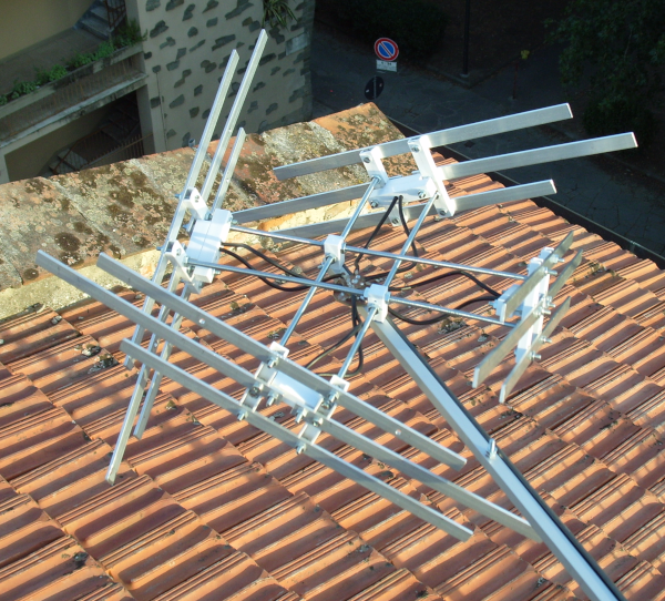
Measurements substantially confirm simulations results; the first tests on satellite reception on 70cm band has show very stable signal thanks to circular polarization and a signal level compatible with the low gain of this antenna. The front-end used for this tests has been built on an obsolete MGA62563 followed by a band filter about 10MHz wide around 435MHz, so, for the moment, the reception performance has not been verified on a wider band.
This is yet an experimental realization (non water-proof either), so no mechanical design is given. Soon a more robust and easy to build version will be released.